LED Pumpkins
Two projects, running in parallel
This started as one goal — learn microcontrollers — that turned into a checklist: SMD soldering, 3D modeling in Blender, batch 3D printing, PCB design in KiCad, and ATtiny10 programming, all at once. Rather than do them one at a time, I ran two parallel tracks: designing and printing the pumpkin shell itself, and building the electronics that would live inside it.
Designing a pumpkin that prints fast and cleans up easy
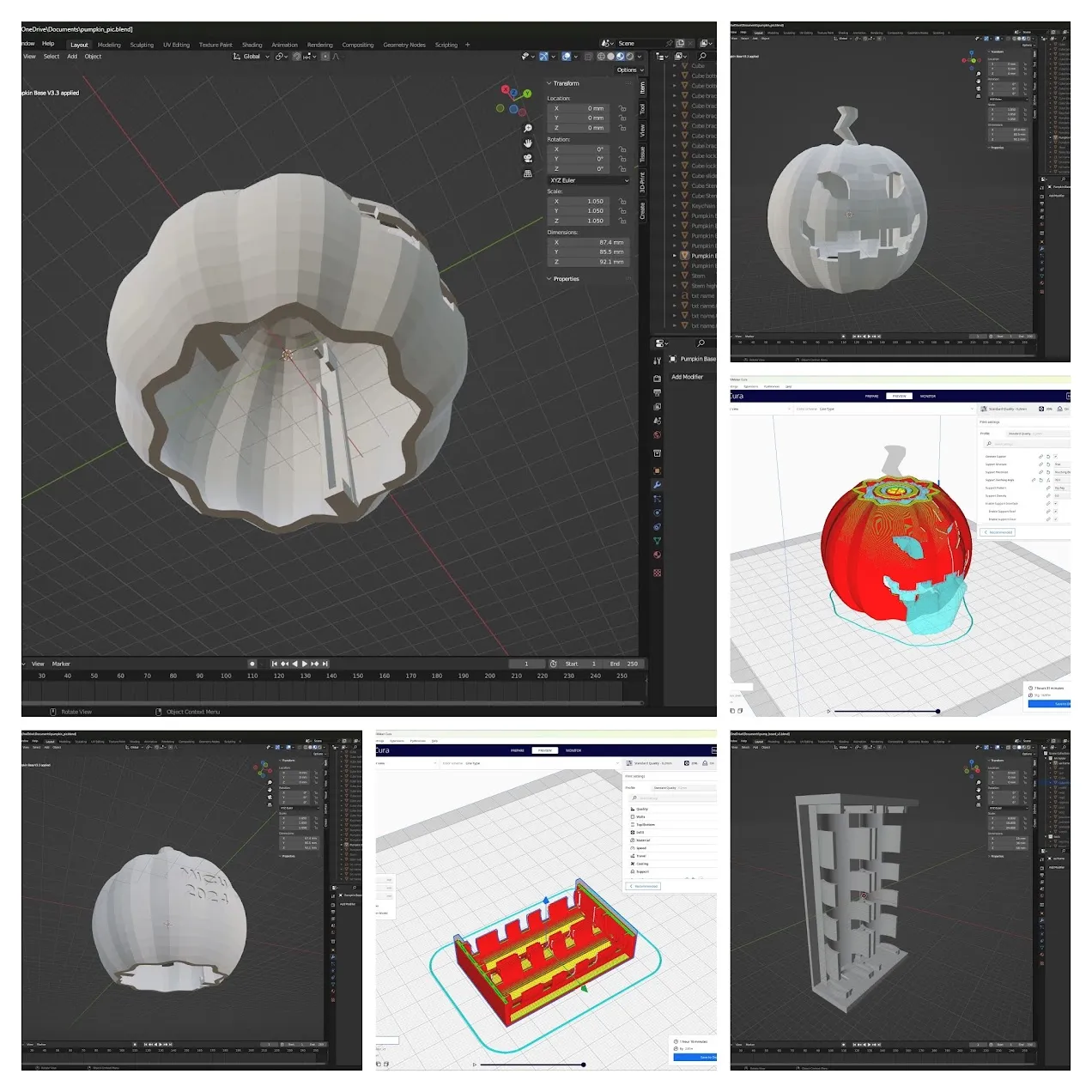
The shell went through several passes in Blender before it was actually usable at batch scale. Early versions of the carved face needed grams of support material on the overhangs and a genuinely tedious amount of cleanup per print. I kept iterating — thinning walls, adjusting the overhangs on the eyes and mouth, angling things to self-support — until it printed quickly, needed almost no support material, and still read as an obviously carved jack-o’-lantern rather than an abstract blob with holes in it. I skipped painting entirely and just swapped filament color between batches; with fifty of these to print, that was a much better trade of my time than a paintbrush would have been.
Getting the ATtiny10 to do anything at all
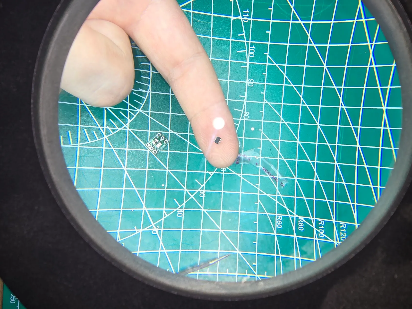
I picked the ATtiny10 for one reason: it was the cheapest chip that could do the job. Getting it to do the job took a while. I was using the Arduino IDE at the time, and its ATtiny10 core is fairly barebones compared to support for other AVR chips — just getting the toolchain to flash the thing and blink an LED took longer than I expected before any of the real project work started.
Picking hardware: PWM, a transistor, and two pins doing double duty
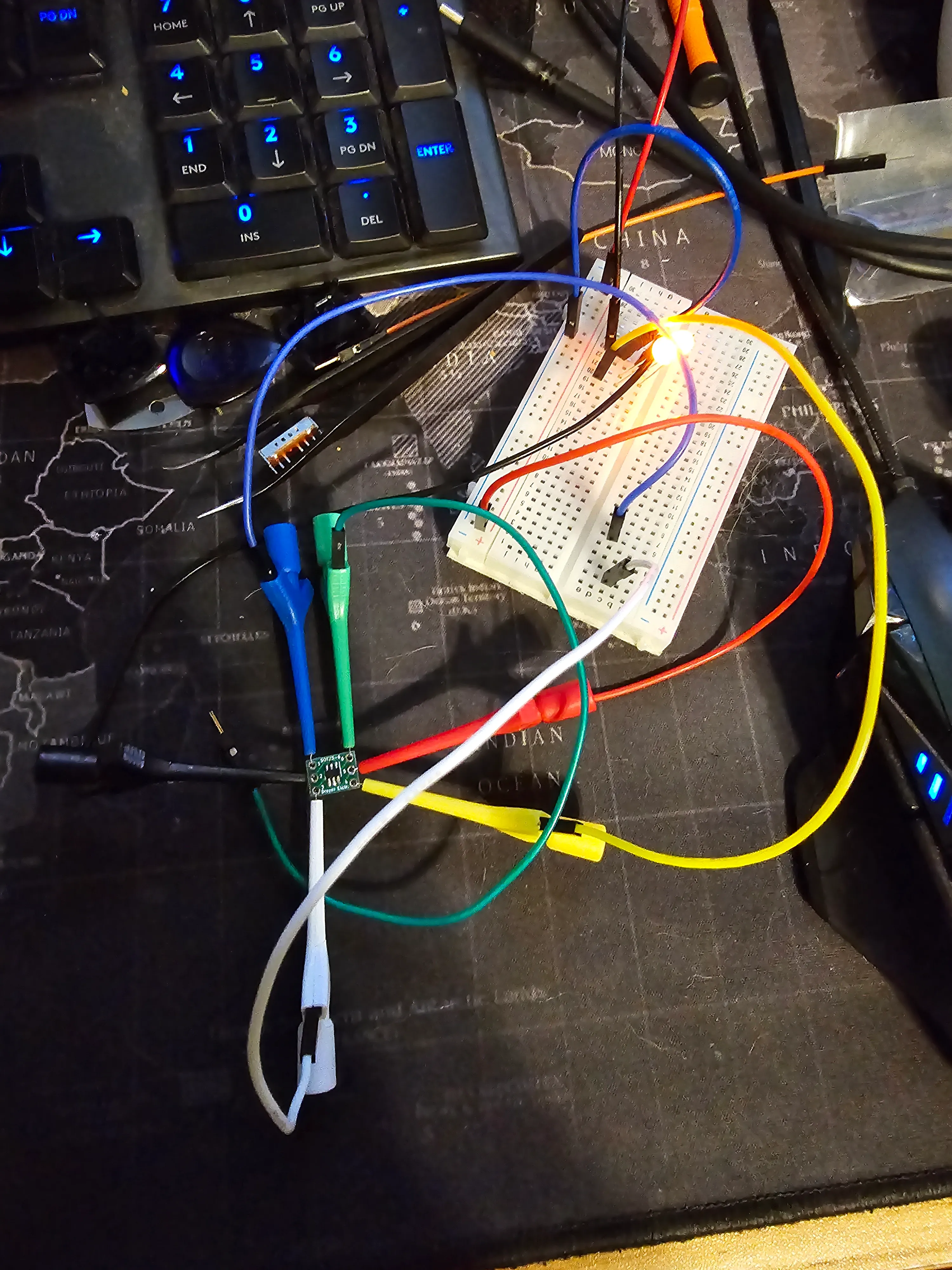
I wanted to stretch battery life without buying more expensive constant-current LED drivers — pennies per unit, but pennies times fifty adds up — so getting a decent PWM setup to cut power draw mattered. I also wanted a few different flashing effects, mostly because a chip that only turns an LED on and off doesn’t really justify picking the ATtiny10 over something even cheaper, and I needed to justify that choice somehow.
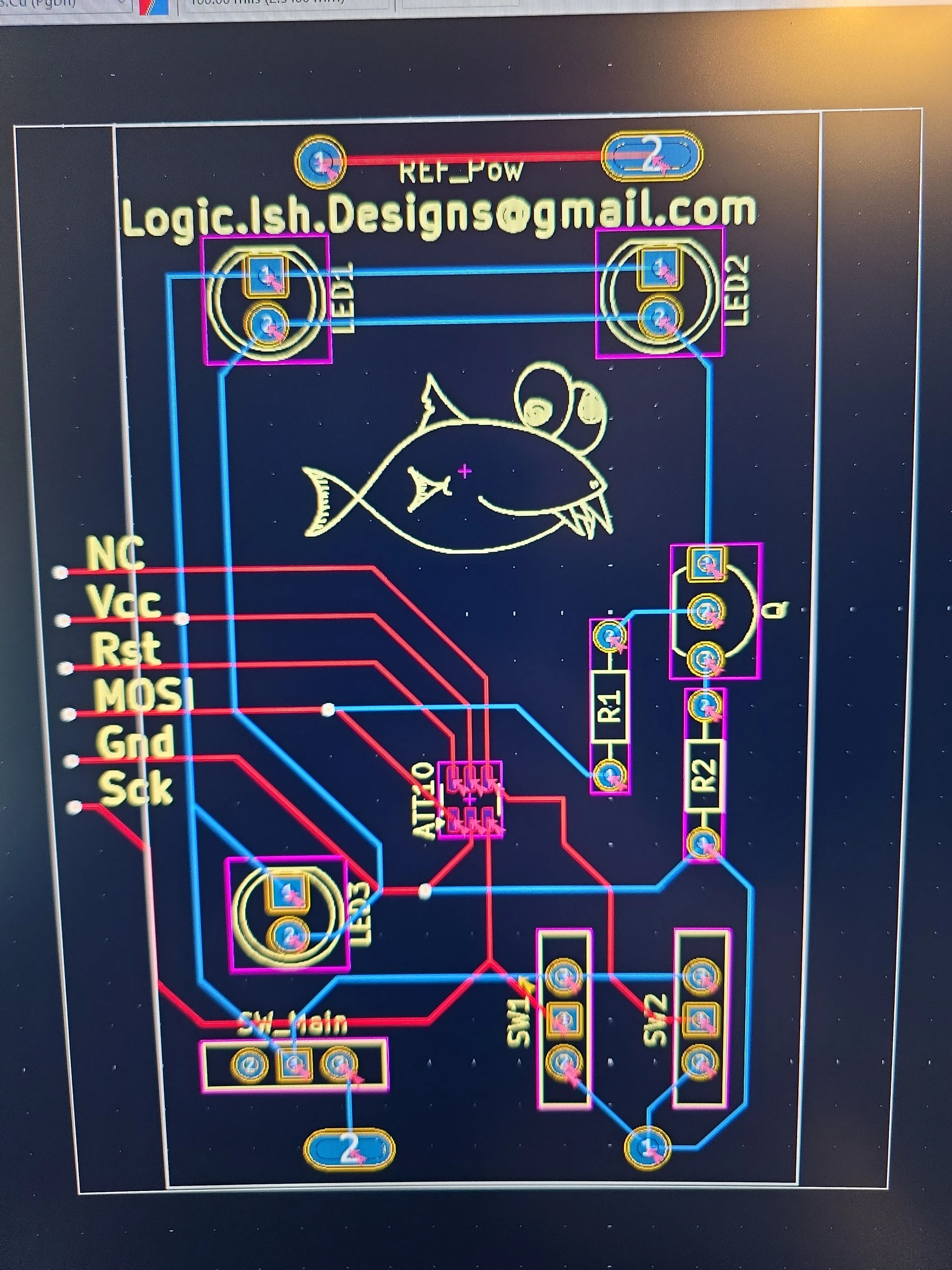
The ATtiny10 only has a handful of usable I/O pins, so the design uses two of them for mode selection and one for LED output. I wasn’t confident the chip could drive the LEDs directly at the current I wanted, so a 2N2222A transistor sits between the ATtiny10’s PWM output and the LED bank — the microcontroller just switches the transistor, and the transistor handles the actual LED current. The two selector pins are toggled directly between hardware-forced high and low (no pull-up/pull-down resistors), giving four combinations for four modes.
The interrupt fight I lost (and the mistakes I kept)
I spent a couple of weeks trying to get interrupts working for mode-switch detection, and never got them working reliably — it turns out that’s a fairly common complaint with the ATtiny10 core under the Arduino IDE, not just me doing something wrong. I gave up and switched to polling the input pins in the main loop instead, which works fine, but left a couple of things I never went back to clean up:
- The
volatile booldeclarations forison1/ison2are a leftover from the interrupt attempt. They don’t need to bevolatilein a polling loop — that was an oversight, not a design choice. - None of the mode loops check for a switch change mid-animation. Mode 2 (the breathing effect) and mode 3 (the candle flicker) both run their full timing loop before the code ever looks at the switches again, so there’s real, noticeable latency between flipping a switch and the pumpkin actually changing modes. Adding an early-exit check inside those loops would fix it. I was frustrated enough about the interrupts not working that I didn’t circle back and do it.
Here’s the actual firmware, mistakes included:
#include <avr/io.h> // for the attiny10 pins and all
#include <avr/interrupt.h> // for PWM
#include <util/delay.h> // for millisecond delays

/*
  Author--- LogicishDesigns
  Date----- July 2024
  Function- Basic controller for ATTINY10 microcontroller to light up led(s).
            Uses two input pins to select one of four different "modes" from
            the user. Output to pin1, designed to push a signal to a switching
            transistor for control of an led(s) lights (mA output limit on the
            attiny10 restricts direct output for more than one led). Pin1 used
            for pulse width modulation to conserve battery life and maximize
            brightness. Pull up/down pins not used with plans for hardware
            forced high/low toggle. Loop used for detecting user input instead
            of interrupts due to problematic/glitchy interrupt sensing on the
            attiny10 model.
  Notes---- Code not optimized. Designed primarily as an education exercise in
            microcontroller design and programming with secondary focus on
            function and efficiency.
*/

/*
  ATTINY10

  1  ~|--|~  6
  2  ~|  |~  5
  3  ~|--|~  4

  1 - pin set to output for led trigger, PWM mode
  2 - ground pin
  3 - input pin for mode selection
  4 - input pin for mode selection
  5 - voltage in
  6 - reset pin, not used
*/

// ----- add some labels for the pins -----
#define in1 PB1 // pin3
#define in2 PB2 // pin4
#define led PB0 // pin1

// ----- some vars that compiler won't optomize so they can
//       be dynamically assigned during run time -----
volatile bool ison1;
volatile bool ison2;

void setup() {
  // setup pins, define which pins are input or output
  DDRB &= ~(_BV(in1) | _BV(in2)); // in pins
  DDRB |= _BV(led); // out pin

  // setup timer
  TCCR0A |= _BV(WGM00); // fast PWM 8bit
  TCCR0B |= _BV(WGM02); // fast PWM 8bit
  TCCR0A |= _BV(COM0A1); // clear on compare (non-inverted)
  TCCR0B |= _BV(CS00); // timer off, for now

  // initiate some stuff
  OCR0A = 1; // set dutycycle 1/255 for PWM (temp)
  ison1 = false;
  ison2 = false;
}

// main loop for operation
void loop() {
  ison1 = (PINB & _BV(in1));
  ison2 = (PINB & _BV(in2));

  int i = 1;

  // mode "1"
  // on at 200/255 dutycycle
  if(ison1 && !ison2) {
    OCR0A = 200;
  }
  // mode "2"
  // log-ish breathing effect
  else if(ison1 && ison2) {
    while(i<100) {
      OCR0A = i + i;
      i++;
      _delay_ms(15);
    }
    while(i>1) {
      OCR0A = i + i;
      i--;
      _delay_ms(15);
    }
  }
  // mode "3"
  // candle like flickering effect
  else if(!ison1 && ison2) {
    int int1 = 180;
    int int2 = 130;
    while(i<6) {
      OCR0A = 200;
      _delay_ms(100);
      OCR0A = int2;
      int2 = int2 + 10;
      _delay_ms(75);
      OCR0A = int1;
      int1 = int1 - 10;
      _delay_ms(100);
      i++;
    }
  }
  // mode "4"
  // blinking effect
  else if(!ison1 && !ison2) {
    OCR0A = 200;
    _delay_ms(200);
    OCR0A = 5;
    _delay_ms(200);
     OCR0A = 200;
    _delay_ms(400);
    OCR0A = 1;
    _delay_ms(400);
  }
}
Mode 2’s comment calls it a “log-ish breathing effect” — half a description of the ramp curve, half a pun I wasn’t going to pass up.
Hand-soldering fifty boards, then not wiring any of them
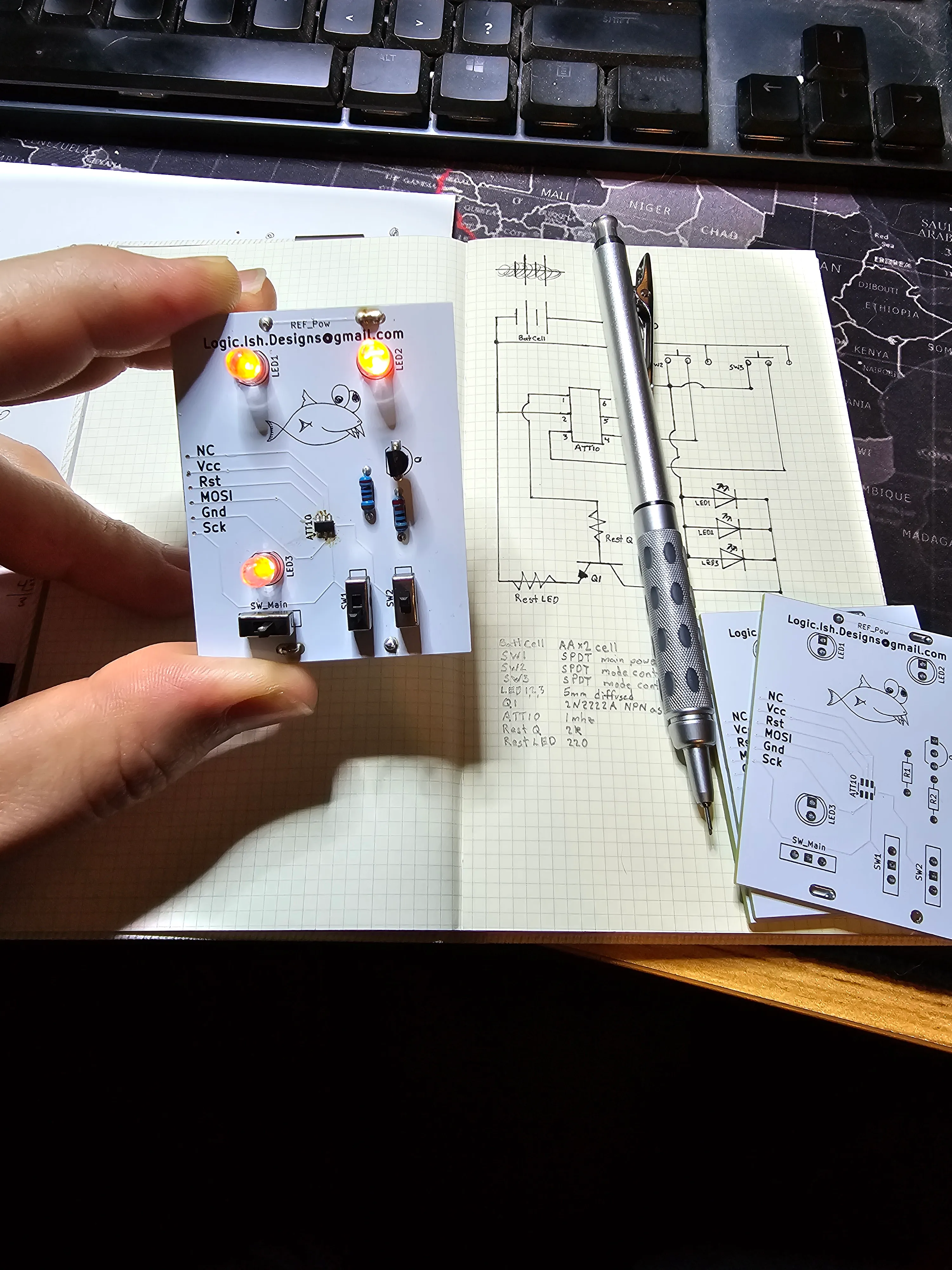
Every one of these boards got hand-soldered, including the ATtiny10 itself, in a genuinely fine SMD pitch that took a while to build real muscle memory for. Three boards didn’t survive the process — bad joints, and at least one chip I flat-out cooked with too much heat for too long. That’s the honest cost of doing fifty of these by hand instead of sending them out for assembly.
Once a board actually worked, though, final assembly needed no wiring at all. The PCB clips onto a 3D-printed battery holder, and since the LEDs only need to shine through the eye and mouth cutouts, the whole board-and-holder assembly just slides up into the pumpkin from the bottom and stays in place on gravity alone — no connectors, no screws, no glue. That also made batching easy: I’d print five to eight battery holders at a time, then a couple of pumpkin shells at a time, and assembly was just stacking parts together.
Where it landed
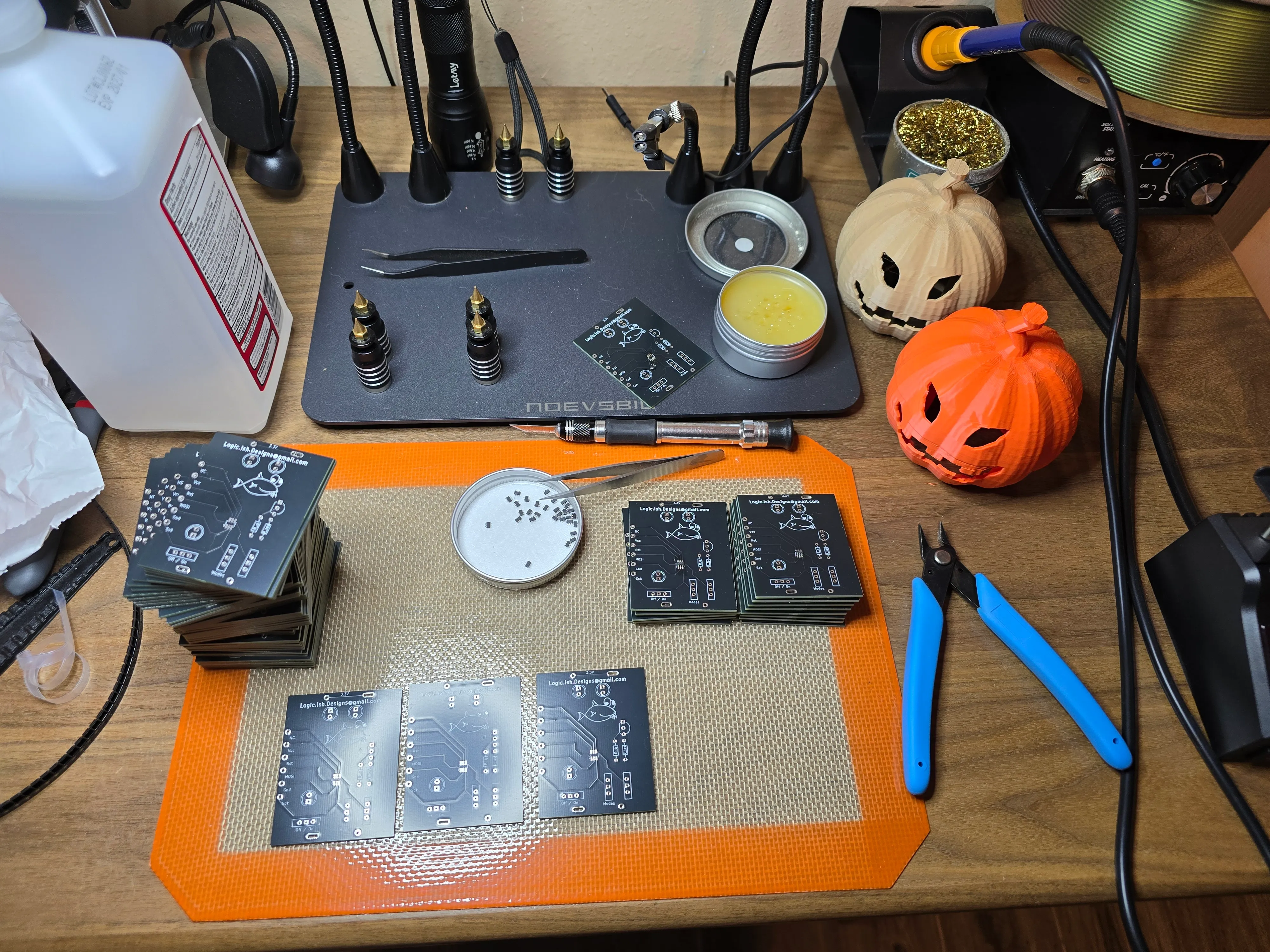
Fifty units, fifty ATtiny10s, zero wires, zero paint. Good enough for a work Halloween decoration, and a genuinely thorough crash course in five different skills I wanted to actually learn.